The Buildings and Infrastructure
Firstly, I am indebted to my colleague Bob Stack who
supplied me with copies of several key drawings of Borenore. These have helped
considerably. If you have a photo or drawing that you think may help, please
forward it to me.
I am leaving the signals out of the discussion for now
as this will be a big project later in the build.
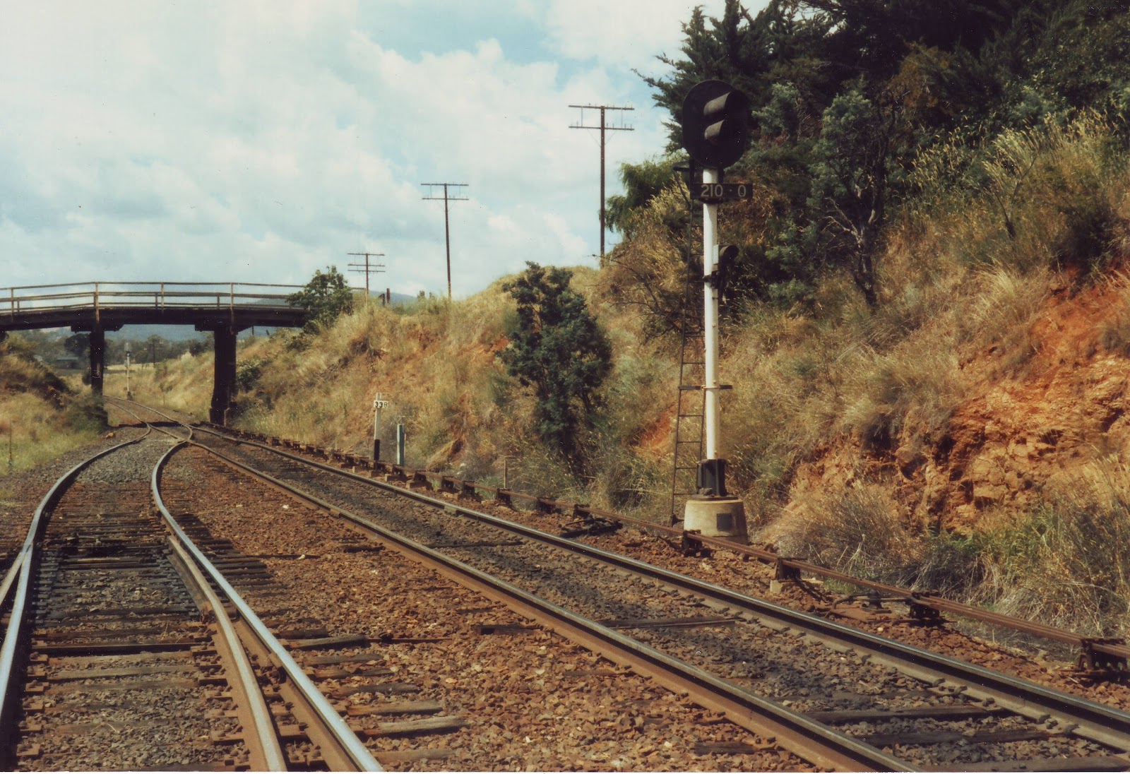
I will start from the LHS as you view the model or
look at the plan from the first post and the first piece of infrastructure is
the Overhead Bridge leading to the goods yard, an elaborate structure for such
a task. It is an angled approach version of a typical NSWGR overbridge.

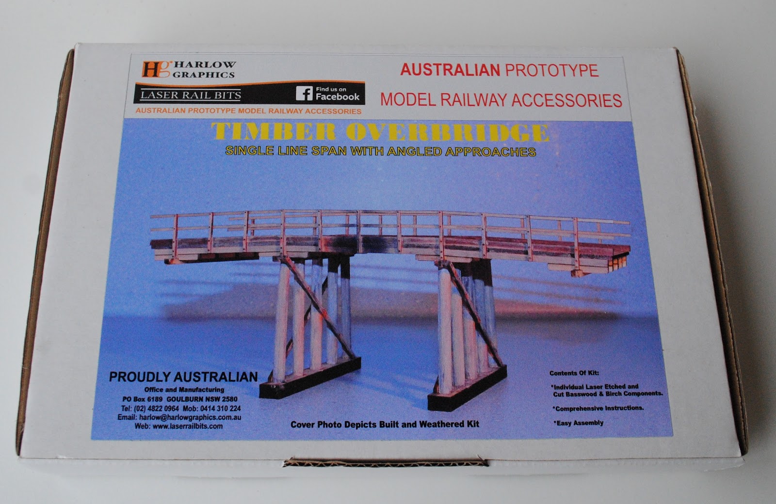
Fortunately, Rod Kelly from Laser Rail Bits makes an
excellent kit of this bridge, albeit not exactly correct for Borenore. After a
“long” enjoyable chat with Rod he offered to “burn” me some modified piles for
the bridge to make it more correct for Borenore.
The next item is the SM’s Residence.

Crop from a Mike Schrader photo.

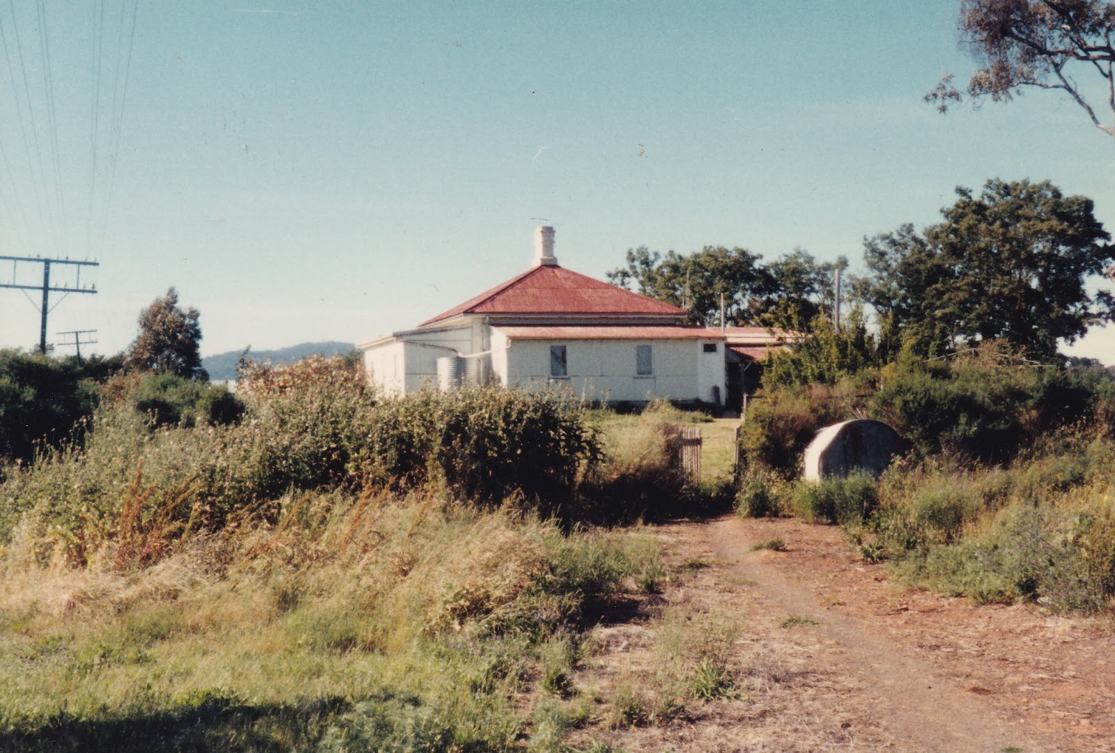
It is based on a Gate Keeper residence and in 1965 was
virtually just that but with an extra chimney. However, it proceeded to get
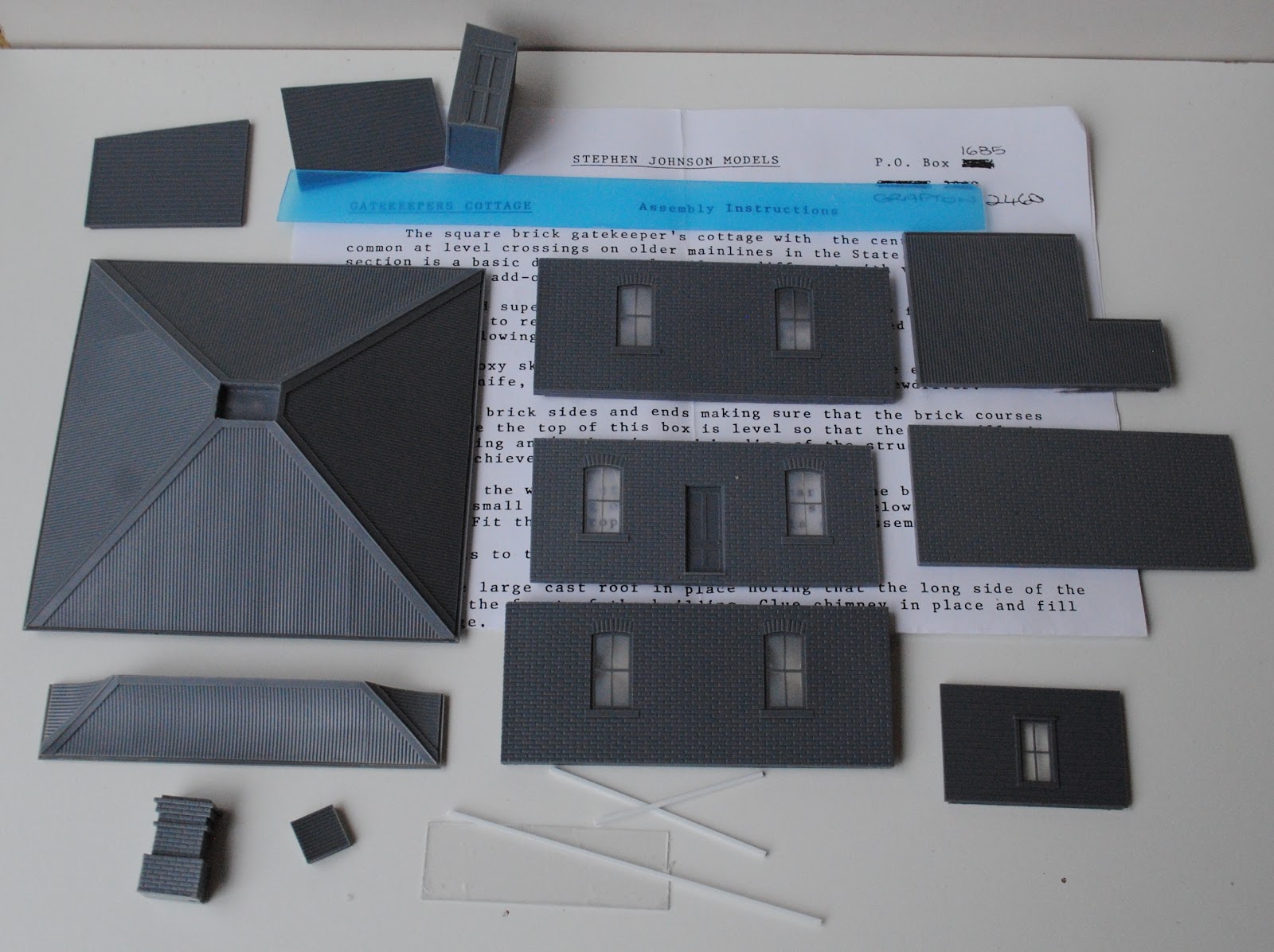
added on to over the years. I am lucky here as Stephen from SJM Models produced
an excellent model of a Gate Keepers house and so this is what will be used on
the model with a bit of extra work. There will be a second one needed for the
level crossing.
One of the drawings I was given by Bob Stack shows it with all the additions, some of which have recently been opened up.

This is a drawing how it ended up.
Next in line are the station buildings consisting of a
Lamp Room, Out of Shed, 3 Room Station Building with attached Toilet and
finally the Signal Box.
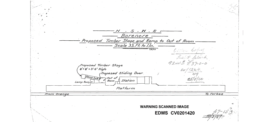

The Out of Shed had a loading race at the rear as seen in the drawing below and the field notes.


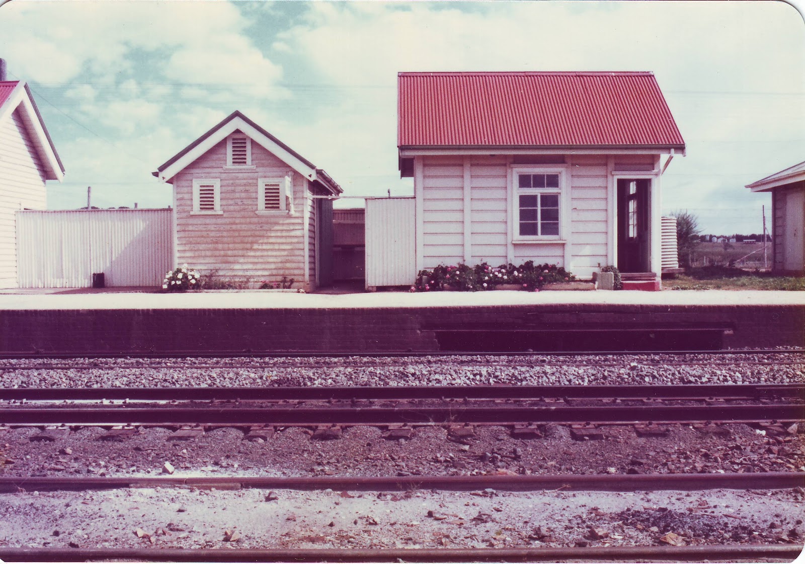
The Lamp Room, Out of Shed and Station Building with
attached Toilet will have to be scratch built. In the late 70’s I measured
these up with the help of my father and friend Allan Garbutt who drew up
excellent field notes as I called out the numbers. Here are a few scans of some
of the pages.


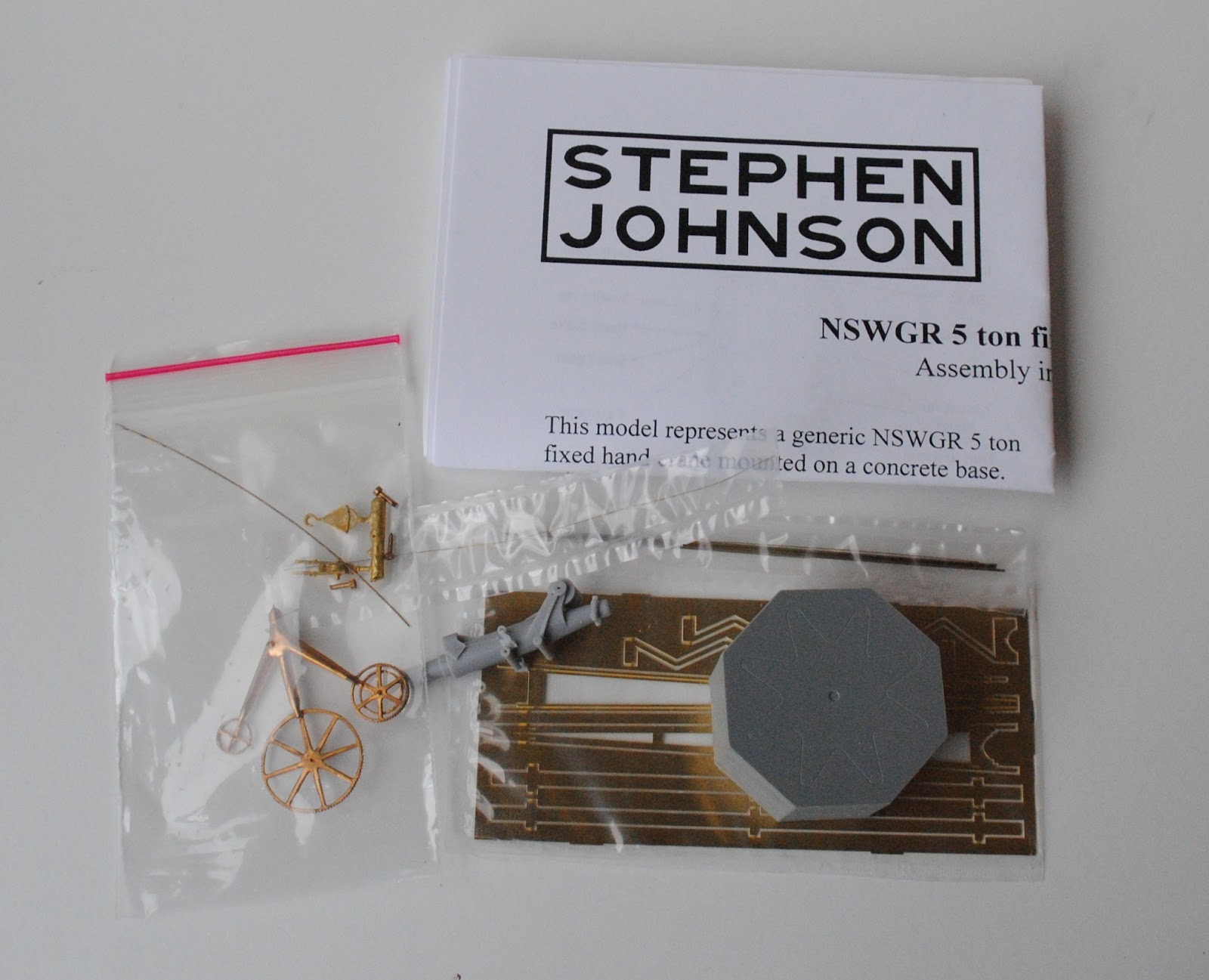
The Signal box is a precast concrete version and SJM
make a fine model of a 4-panel box so I asked very nicely and Stephen cast me
an extra back for the kit which has allowed me to cut and paste it into a 5-panel
box.


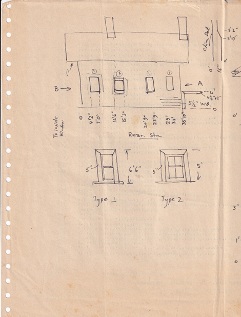
Finally, across the tracks from the platform is a G3
goods shed, a gantry crane, loading bank and stock race.
When first built the goods shed had the customary
office attached but by 1965 it was gone as in these 1978 views.

This will be a slightly kit bashed Ian Lindsay Models G3
Kit and an SJM Gantry Crane Kit.


Rod Kelly makes a low timber loading bank that will be
the basis of the one at Borenore, but I will probably need two kits.


The stock race will need to be scratch built and
shrunk to fit.
There is also a tank car unloading point on the
extension of the stock siding, but this is only a couple of pipes sticking out
of the ground.
I have deliberately avoided discussing the large
number of detail items that will be needed for the time being like platform
scales, seats, etc. which will come from the SJM collection. Now to the build
process. I will put up a post on each project as I build each item.
All photos by the author except the one credited.
Cheers Phil Collins


.jpg)