Thursday, February 24, 2022

THE MODULES 


Firstly, why use modules? I decided to use modules for two reasons: portability and the ability to turn a module on its back and sit on a stool and work on point motors, wiring, etc. I will talk and show more about this in a later post. The modules for BORENORE are made from Capral 25mm square aluminum tube and Capral Qubelok Joiners.
 

A similar product can be purchased from the big green warehouse, but it is much cheaper to use the Capral (Australian) product. Capral sell the tube in 6m lengths but will usually cut it in half or thirds to facilitate transport. I am not sure if they do “cut to size” but they do charge per cut. You could probably buy a cheap drop saw for the same price. However, you will need to have say a 64-tooth blade to cut the aluminum tube. These usually cost as much as the drop saw itself. I first saw a module built using these products in a tutorial by an innovative narrow-gauge Victorian modeler named Mario Rapenitt.


There are other examples on the internet. If my memory serves me well, I think Keiran Ryan drew one up for his website once, but I thought it was a bit over engineered and expensive. The BORENORE modules are based on a basic 1200mm x 600mm x 150mm “box” frame. I chose this size because it suited MY needs, but you can build them any size you want; although I would think 1800 mm long would be the practical limit. The 150 mm depth provides the necessary clearance for point “motors” etc. These 1200mm long modules are extremely light in weight. The home installation has corner modules which are based on a 900mm L Shaped Module but for exhibition there will be 1200mm return modules using 3D printed 45-degree joiners printed for me by Keiran Ryan of KRM. These modules will be discussed in a future post. 
The modules are joined using 18mm 7 ply inserts in the ends. You can also put the “end plates” in the side of a module if that is what you need. 
This is where the Capral product range comes into its own. They produce an extruded tube with a “Lip” on one side. I use this “Lip” to help locate and secure the end plates. Clip from Queblok PDF. 


The end plates are held in place by Zenith 8G x 15mm Gold Passivated Button Head Timber Stitching Screws - 40 Pack


from behind using the Lip to hold them in place. I also use the same screws for securing the ply deck. 
The modules are aligned using DCC Concepts Legacy Models PowerPoint Baseboard Dowels (4-pack).


These are not cheap, but they work for me. DCC Concepts also sell alignment dowels without the electrical contacts. The wiring on the show modules is quite simple so an alignment dowel that also acts to carry the power bus is perfect. The modules are then held together using furniture bolts and T-nuts. Yes, no washers to get lost.

The modules are topped with 7mm 5-ply which I do buy from the big green warehouse in 900mm x 600mm sheets, it is simply easy that way. The scenery base is 20mm thick extruded polystyrene sheet.
 
Tools needed. 
A drop saw for cutting the aluminum tube and other jobs. 
64 tooth blade. 
A Table saw or similar for cutting the various pieces of ply. 
A two-speed battery drill/driver. 
3mm, 6mm and 7.5mm drill bits. 
13mm and 19mm spade bits. 
A soft face hammer. 
Steel rules and squares, various markers. 


Bill of Materials for 1200mm x 600mm x 150mm Module. 

4 x 575mm long 25 mm square aluminum tube 
6 x 550mm long 25 mm square aluminum tube 
4 x 550mm long 25 mm square aluminum tube with Lip 
4 x 100mm long 25 mm square aluminum tube with Lip 
2 x 100mm long 25 mm square aluminum tube 
8 x 3-way Qubelok joiners 
4 x 4-way Qubelok joiners 
2 x sheets of 7mm ply 900mm x 600mm 
2 x end plates, 550mm x 100mm x 18mm 7 ply. 
2 x alignment/power dowels. 
2 x M6 T-nuts 2 x M6 x 50mm Furniture Bolts 
18 x 15mm 8G button headed screws. 
Suitable Extruded polystyrene foam for scenery base and landscaping. 
3 mm MDF for Facias and Backdrops. 


All the components laid out ready for assembly. Including the 7 mm 5 ply deck and 20 mm extruded polystyrene board. 


                                     The Qubelok Joiners 


The end tubes showing the “Lip”. 


 All the Lips need to be cut at 45-degree angles to provide clearance when assembled. 


Design Tip: Before you design each module firstly draw up the track plan on some butcher’s paper to see where any points may interfere with the framework. It may be necessary to move the centre beam or slightly adjust the track plan so points do not coincide with framework. All of my modules are slightly asymmetric simply to assist in marking out and cutting the tube. 

Assembling the basic frame. 
Nothing could be simpler. Layout the frame “plan”. 
Hammer the joiners into the tube. 
Fit Risers. Build a top frame. 
Add the Top Frame to the base. 


                              Photo1 End Frame Layout 


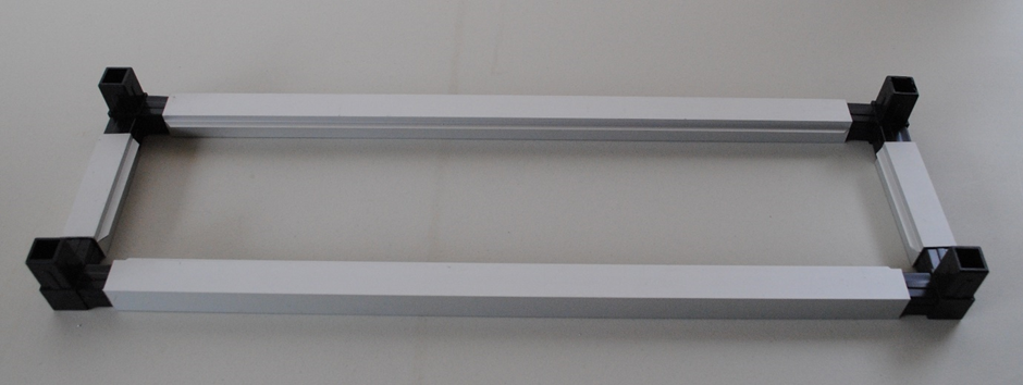
 Photo 2 End Frame ready to knock together. 


Photo 3 Finished End Frame and set up for Centre Frame. 


Photo 4 Two End Frames 


 Photo 5 Assembled Centre Frame 


Photo 6 Final Assemble Layout  


Photo 7 More Progress 


Photo 8 Frame Almost Complete. 

Photo 9 Completed Frame 


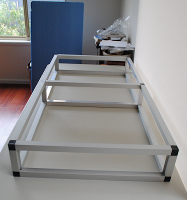
Photo 10 A different View 


Photo 11 7mm ply laid out. 


Photo 12 Ply in final position 


Photo 13 Extruded Polystyrene Foam in position. 

 In the next post I will discuss the End Plates. 

 Cheers Phil Collins

Tuesday, February 22, 2022


Borenore the Model

Photo by P H Collins

This blog serves to document my journey of building a H.O. Model of the railway facilities at Borenore Circa 1965.


Borenore is a small village on the Central Western Slopes of NSW. It is situated mid-way between the main town of Orange and the smaller town of Molong. While the “village” is somewhat spread out, the main concentration is around the railway station which is situated on the now main Western line between Sydney and Broken Hill and more specifically the towns of Orange and Molong. The Station is located 210 miles/336Km west of Sydney Central.

The railway line from Molong to Orange is on an almost continuous rising grade of 1 in 50/40 before dropping back down to Orange. Accordingly, trains working over this section required assistant engines to negotiate the grades. This double heading produced some spectacular working. Borenore station provided a crossing loop on the single track at approximately the halfway point between Molong and Orange and accordingly was a mecca for rail enthusiasts.

The railway infrastructure at Borenore in 1965 consisted of a crossing loop and goods siding with a short extension to the goods siding serving a stock race and tank car unloading point of H C Sleigh (Golden Fleece). There was a small three-room station building with attached toilet facilities, a signal box, out of shed, lamp room and G3 Goods Shed with adjacent jib crane. There was also a small/low loading bank and an over bridge to give access to the goods facilities. Accommodation consisted of a house for the ASM which was in fact a Gate Keepers House. These items will be discussed at length in a later chapter.


Safe working consisted of lower quadrant semaphore signals and miniature electric staff. A later chapter will elaborate on these.

Why model Borenore.

I have a family connection to Borenore as my aunt spent several years stationed at the St Joseph’s Convent located on the aptly named Convent Lane. The family visited her on numerous occasions when I was a small child. My great grandfather settled at Forest Reefs, east of Orange, in the 1840’s after migrating from Ireland and my grandfather spent most of his life in the Orange and Cunnock Districts. Accordingly, when I became interested in railways and railway modelling in the early 70’s I was attracted back to the district and in particular to Borenore. I began to research the railway history of Borenore and more generally the line from Orange to Molong and accordingly decided that one day I would like to build a model of Borenore. That day has finally arrived.

During the early part of my renewed interest in trains/modelling there was a weekly serial publication on Australian Trains available through the newsagent. In one issue was this photograph.

3638+6011 No604 Goods Jan 1967 Photo. Michael Schrader


It was taken by the Late Michael Schrader and shows 3638 + 6011 on No 604 departing Borenore for the east. I was now truly hooked. So much so that I contacted Michael via ROA to see if I could acquire an enlargement of the original slide. To my surprise he replied saying he was very busy but enclosed the slide for me to arrange the print. This photo is a scan of a duplicate of that slide. The slide was promptly returned, and it appears that Michael’s slide collection ended up with Train Hobby Publications as the photo appeared in the 36 Class book. Soon after my late father along with my great friend Allan Garbutt and I returned to Borenore to photograph and measure the buildings.

Why them has it taken so long to get started? Well, that is a good question, but a recent house move that necessitated the demolition of the main station/yard of my model railway meant I had to start again and Borenore became the hopefully achievable result.

Borenore the model will be initially built as part of my home layout, but it is intended to transition to an exhibition layout in time. It will be built using light weight modules made from Capral Qubelok and 25mm aluminum tube and plywood. My experience with the Epping Club’s exhibition layouts and my own modular branch line terminus has convinced me to try and build a better mouse trap!

The blog will document this journey as I venture into the somewhat unknown world of aluminum modules, Fast Tracks trackwork and much more. The next chapter will discuss the building of the modules.

In the meantime, here are some of the references I have used.


Railway Photographers. Without who’s published photographs this model would never have been built including but not exclusively Laurie Anderson, Michael Schrader, Ray Love, Graham Cotterill, etc.


Finally, a great paper on Borenore by Stuart Sharp.

https://arhsnsw.com.au/wp-content/uploads/2018/08/K-Borenore.pdf

Cheers Phil Collins

                                                                   Important Update Well, it has been longer than I had planned since the ...