I probably should have posted this article earlier. On
my former layout at the previous home, I built a storage traverser. It was, and
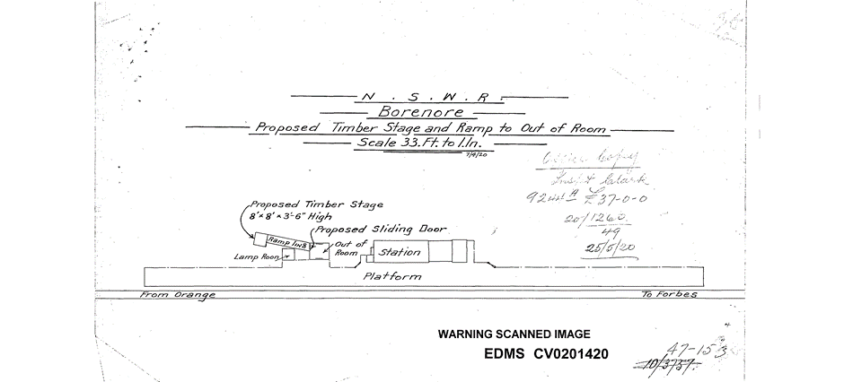
still is 2.68 M long. It has now been re-engineered for use with Borenore and
my branch line terminus called Balowra, a kind of mirror image of Eugowra that
is now being enhanced a little. Balowra also survived the move.
The re-engineering comprised of ditching the old L-Girder benchwork and risers
for direct mounting on two1.5 metre steel sliding door cabinets, which can also
store train storage boxes into the future. The new arrangement gives an
infinitely more stable base and better functioning traverser. I can now move
the traverser in and out by one hand without any binding. The sliders are now
mounted flat instead of vertically. I am still to build the connection to the remainder
of the railway but that will come as Borenore gains momentum.
The original traverser was the subject of a presentation at Modelling the
Railways of NSW, a joint presentation with my friend and colleague, Allan
Garbutt. It was re presenter at an NMRA Convention in Canberra. With Allan’s
permission I am posting the presentation here.
The new version is shown in the photos below.

The new deck fitted to the storage cabinets, the branch line models can be seen on their side in the background.

The new deck canter leavers over the cabinets

Traverser table refitted
Track isolating system using micro switches
Table at full extention
Dust covers fitted, a must have.
The original MRofNSW Article reproduced.
Storage Yards
Building a better mousetrap
Presenters:
Phil Collins and Allan Garbutt
Introduction
Operational Storage has traditionally been represented by a
series of loops or single-ended sidings to store trains off-stage. The purpose of operational storage is to hold
as many full-length trains as possible and to provide “the other end” of the line. Unfortunately, traditional yard loops can be
expensive and reduce the amount of available storage space by up to 60%.
Traversers were used on the prototype to move a carriage or
locomotive from one track to an adjacent track in a confined location. An example of a prototype traverser can be
found at the Sydney Tramway Museum, Loftus.
This traverser originally came from the Clyde Engineering workshops
at Granville.
Within our model railway we can use the principle of a
traverser to great advantage to maximise operational storage within our staging
yards.
In model storage terms a traverser is much more like a well
built draw - and not limited to moving a single car at a time!
Traversers within model railways are not a new idea. There have been several articles within Model
Railroader and other model railway publications that describe various methods
of making a traverser. Commercial manufacturers
What we will be describing are the advantages and the tips
and tricks in creating a manually operated horizontal or vertical traverser.
The Horizontal Traverser Storage System
by Phil Collins
I first decided to use a traverser type storage system on my
second railway at my current home as the simple ladder yard system would give
me only about 40% of the storage capacity that a traverser would give me. I was
inspired by an article in December 2000 Model Railroader by John R. Signor.
However at the time I could not find suitable drawer slides so I settled for a
cassette system, albeit unwieldy. Sometime later a friend came over for morning
tea as part of his recovery from an operation and we got talking and within
minutes we were on the internet and found the drawer slides I needed. It is
good to have a mate who is a builder. A
quick trip to Wetherill Park the following week and I had two pairs of Hafele
Part No 422.83.345 drawer slides and the rebuild was underway.
These drawer slides had a load rating of 45 kg per pair and
were the fully extendable type. I calculated that a fully loaded traverser
would weigh approx. 39 kg, however I decided to use two pairs of slides (total
capacity of 90 Kg) to ensure stability over the 2.68 metre length and 0.45
metre width of the traverser.
The sums in favour of a traverser are indisputable. The cost
of two pairs of slides was $37.37, only slightly more today, verses
approx. $300 for the point work for a
ladder yard and the bonus is 2.5 times the storage capacity. You can see how
this factor of 2.5 is arrived at by comparing the two photos of my traverser
and a ladder yard overlayed on the deck. In the 0.45 metre width I was able to
lay 8 roads at 50 mm spacing, the remainder of the width being taken up by the
aluminium angle bracing used to stiffen the deck over its length.
1
Horizontal traverser in use
2
Example yard ladder in the same space
After some research I decided to use Trackrite urethane
track underlay on the deck. This had two benefits. Firstly it greatly reduced
noise, compared with say cork, and secondly its accurate 50 mm width made it
easy to locate the track. The Trackrite simply lays on the deck between the
aluminium edging, it is not glued down. The track sits in place and is held
there by one set of dropper wires and printed circuit board sleepers at the
ends.
The most difficult task in the building process was to
develop an indexing system to align each road with the on/off roads at either
end of the traverser. I finally settled on patio bolts aligning with holes in
more aluminium angle. Once each position was indexed the track was soldered to
the printed circuit board sleepers using a track alignment jig. The final task
was to install some form of isolating system for each road. When say road 6 is
aligned, roads 1,2,3,4 and part of 5 are sitting out over a 1 metre drop so
power to roads sitting out over the “drop” as it were needs to be cut off. I
achieved this by a series of micro switches under the deck working against an
aluminium angle fixed to the structure below the deck. The formula here was
simple. The micro switch cuts out power
to the track as each road moves out of alignment over the drop by half a track
width. This is very important as the layout is a DCC controlled railway with no
normal blocks, only the eight created by the isolating micro switches.
I guess the key to any engineering design is whether it
works. Well in this case it works extremely well. The only issues so far are
those associated with retro fitting it into an existing structure and ensuring
vertical alignment of the tracks. This problem is amplified in my case by the
structure sitting on a carpeted floor. Fortunately I have lots of 0.005 inch
styrene spacers at the ready! It is regularly abused by the members of the
NSWDCC Group and did not miss a beat during a visit by 70 members of the NMRA.
I might add that I used code 100 rail on the traverser and on/off tracks
transitioning to code 70 on the main layout section. This was largely due to
having the code 100 left over from a previous project but if I were building
one today from scratch I would not hesitate to use code 70.
The Vertical Traverser
By Allan Garbutt
The vertical traverser has some advantages including not
intruding into the horizontal aisle space, provides dust-free storage and
doubles as a display case.
The items to consider when designing a vertical storage and
display traverser are:
• Depth
required is a mere 130mm (5”)
• Wall Space
Allowance (Height);
The height above and below the approach track needs to be no
more than the total height of the traverser.
The length of the traverser needs to be balanced against the
total weight of the materials used and the number of tracks that it will
consist of. This particular vertical
traverser fits behind a door and uses 1200mm (4’) of wall space in the corner
of the room.
A pulley guide rope and counter weight was used to readily
shift the traverser through its range of movement. Movement is done by simply pushing the box up
or down and allows it to quickly move between any track in the display unit
(Random Access Storage).
The pulleys hold the weight of the traverser and the counter
weight. The entire traverser, including
trains can weigh in around the 25kg mark.
Make sure to check the load rating of the pulleys that you select. Exceeding the load rating could be dangerous
to the health of your trains. The
pulleys selected are made by Cowdry and support 30kg’s each.
The counter weight needs to balance the weight of the
storage unit including trains whilst remaining relatively thin. The material used is a cast iron BBQ hot
plate with some extra weight as required.
The weight required varies depending on the size of the display unit and
will need to hold the full weight of the display unit and an average load of
trains. The example traverser needed up
to 20kg+ once it is filled with trains.
Tracks must align within a fraction of a millimeter both vertically
and horizontally to ensure reliable operation of trains when entering and
leaving the display unit.
Cowdroy TRIUMPH Sliding Door Track System was used as a pair
of vertical guides. These ensure that the traverser moves smoothly and evenly and
stops unwanted horizontal and diagonal movement. The slides act as guides only and do not
carry any weight. The vertical slides
need to have a minimum tolerance to ensure correct track alignment.
The unit is locked in place by a patio security bolt. This security bolt has minimal manufacturing
tolerances and a built-in centre punch marking spike. This ensures accurate marking for drilling
holes to align the traverser and the approach track correctly.
Using these components will avoid damaging the approach and
storage tracks.
The traverser is used with both DCC and DC. A plug-in jumper cable is used to link to the
main layout bus. This pair is connected
to each track via a SPST isolation switch.
The SPST switch isolates one rail.
The traverser is operated by hand and the use of a SPST switch kept the
complexity to a minimum.
I used a quality piece of 9mm 3ply plywood for a flat back
panel. My main criterion was that the
back should be thick enough to take screws.
The shelves need to be cut square and straight to ensure
that they join at a 90 degree angle with the back panel. I recommend using a table saw or getting them
professionally cut. Normally your
supplier can do this for a small fee per cut.
Use a spacing jig to help ensure each shelf is correctly
spaced at approximately 4”.
3mm Perspex is used on the front because it is relatively
self-supporting and minimizes sag. Plastic
channel surround is attached to the top and bottom of the front to allow the
perspex to easily slide on or off. Some
C and H mouldings from Australian Plastic profiles, available from Mitre 10, were
used to manufacture a frame to hold the perspex. The parts used were 10mm x 2.4m Cap moulding
@ $5.50 for 9mm shelves and frame and 4.5mm x 2.4m “H” moulding @ $2.50 which was
cut to a “C” shape.
Atlas Code 100 rerailers (part # 150-844) are used at each
end of the traverser to make sure that each car is on the track as it enters and
leaves the traverser. An adjustment
screw and washer hold down the Atlas rerailer.
This screw and washer allows for a fine adjustment of the vertical
alignment of the track.
Code 100 track was used for the storage tracks. Trackrite urethane track underlay was used to
maintain correct track location on each shelf.
All track is laid loose on the underlay and does not need to be glued
down to the shelves.
3 The Vertical Traverser
Materials Listing
Interesting Internet Links:
http://www.youtube.com/watch?v=dxRJ9rdyX4c
I would be happy to upload the Poerpoint Presentation as well but as a novice I do not have any idea how to do that. If you know how let me know.
Thanks for viewing.


.jpg)


.jpg)


.jpg)