THE
END PLATES
In this post I want to show the End Plates of the
modules and how the modules are joined.
Photo No 1
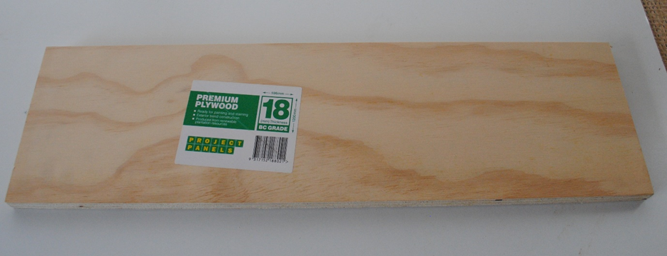
In Photo 1 is the 18 mm x ply that the end plates are made from. I discussed earlier the tube used on the ends of the modules has a lip 17 mm from the edge and to fit the end plates into the ends approx. 1 mm has to be taken from around the inside edge of the plates. I described this in Post No 2.
Photo No 2

In Photo 2 you see the end plate from the outside of the module. These end plates are 550 mm wide x 100 mm high. 4 holes are drilled along the centreline of the plate. Two holes are for the alignment dowels and two for the securing bolts. I chose 75 mm from the edge for the securing bolts and 125 mm from the edge for the alignment dowels. This is not empirical and can be varied to suit a particular situation. The alignment dowels reference and instructions are here:
https://www.dccconcepts.com/manual/powerpoint-dowel-installation-guide
The securing bolt holes are simply 6 mm holes with a
T-Nut behind fitted behind one plate (Hole part drilled say 7.5mm) and the bolt
screwed in from the other plate. In the photo you can see a pair of powered
dowels and the alternate non powered dowels (Shown here but not used).
Additionally, you can see the furniture bolt and T-Nut. The 5th hole
on the bottom right of the plate is a 19 mm hole to allow the DCC Control Bus
to daisy chain from one module to the next.
Photo No 3

In Photo 3 you can see the alignment dowels projecting through from the front (Note one of each type for the photo but two powered ones on my modules) and one furniture bolt with a T-Nut ready to be “pulled” down into the plate. Hopefully you can also see the relieved area around the edge reducing the thickness to 17 mm.
Photo No 4
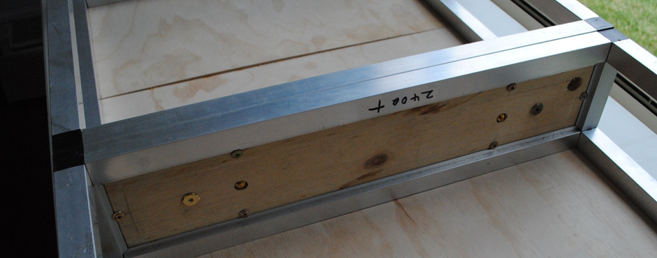
In Photo 4 you can see the end plate fitted up against the afore mentioned “Lip” of the tube plus the 6 button headed screws holding the plate in place against the “Lip”.
Photo No 5

In Photo 5 you see the fitted end plate on No1 module showing the male dowels, holes for the Furniture Bolts and the hole on the LHS for the DCC Control Bus.
Photo No 6

Photo 6 shows the No2 module with the female dowels, holes for furniture bolts and DCC Bus hole.
Photo No 7

Photo 7 shows No1 Module from the inside.
Photo No 8

Photo 8 shows the inside view of No 2 Module. Note the DCC Bus holes aligning now in the top RHS.
Photo No 9

Photo 9 shows the two modules lined up ready to dock together.
Photo No 10

In Photo 10 the modules are joined together ready for securing with the furniture Bolts.
Photo No 11

In Photo 11 the two modules are joined, and the furniture bolts have been screwed in using a nut driver.
Photo No 12

Photo 12 shows the nut driver at work and to the left the alignment dowel with the electrical connection protruding.
Photo No 13

Photo 13 The Alignment Dowels ready to dock.
Photo No 14
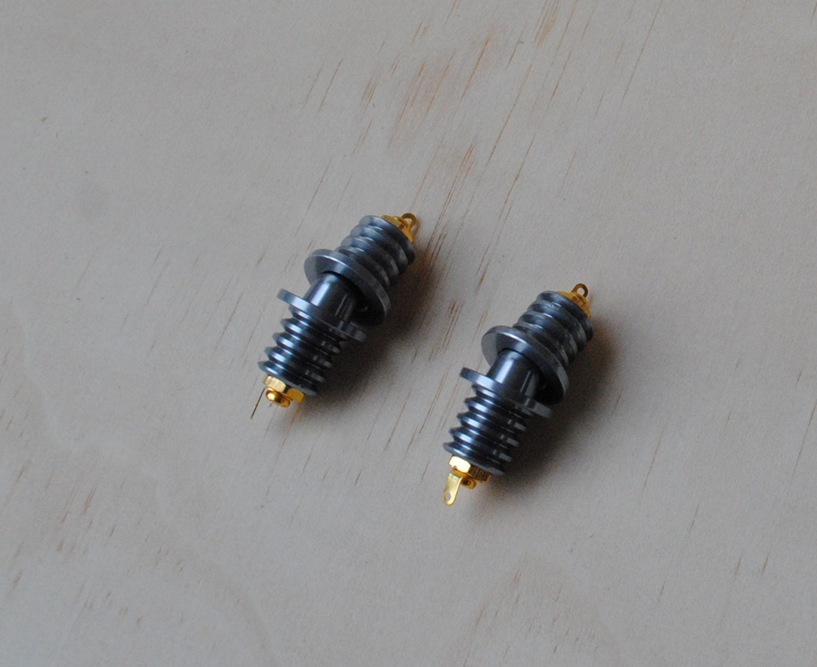
Photo 14 The Alignment Dowels docking.
Photo No 15

Photo 15 Shows the Furniture Bolts and nut driver.
In the next post I will show the modules assembled
into the home layout format along with schematic drawings of both the Home and
Exhibition Arrangements. Currently these drawings are being prepared for me by
a friend.
Cheers Phil

.jpg)
No comments:
Post a Comment